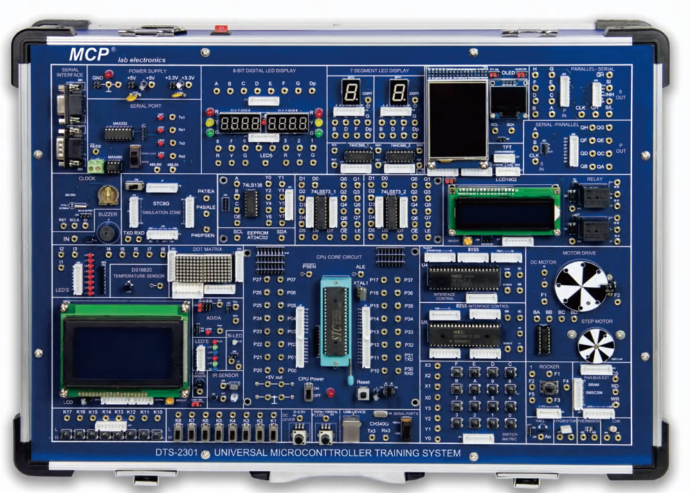
DTS-2301 UNIVERSAL MICROCONTROLLER TRAINING SYSTEM
BDT 89,802/-
Product Details
Brand: MCP
Model: DTS-2301
Country Of Origin: China
The DTS‑2301 Universal Microcontroller Training System uses an aluminum alloy frame box, and the front of the experimental base plate is painted with component identification diagrams, corresponding to the installation of DIP components, making it easy for students to understand the components. The back of the experimental board is installed using the SMD process, and the entire board is accompanied by circuit diagrams and PCB diagrams, making it convenient for users to learn and reference.
The main CPU core board is pluggable and replaceable, and can be STC STC12C5A60S and Intel AT89S52. You can also replace the core board with AVR, PIC, MSP430, STM103 series, ARM7, CPLD, FPGA.
The user downloads the experimental program from the PC to the CPU of the core board for operation through an RS232 cable or USB cable. You can also conduct simulation experiments on the program through a download cable.
The microcontroller I/O port and digital integrated circuit port are both led out with 1mm pins and 2mm gold‑plated sockets, which can perform specified actions (experiments in the experimental guide book) and facilitate various expansion experiments. The spacing between 1mm pins is 2.54mm, and during the experiment, 1mm pin cable can be used as the connecting wire.
The hardware module has 1–2 application routines, providing engineering templates and source programs, and each example has a burned file for user reference. The chips used in the hardware module have detailed functional introductions, circuit schematics, and application cases. This experimental box is widely used for experimental training in various undergraduate and vocational colleges.
Hardware Modules
-
Serial communication module
-
485 communication module
-
Serial to parallel module
-
Parallel to serial module
-
Dual color dot matrix module
-
Eight digit Nixie tube module (dynamic scanning)
-
One bit Nixie tube module (static drive)
-
OLED module
-
1602 LCD module
-
12864 LCD module
-
TFT color screen module
-
SD card module
-
DS1302 clock module
-
74HCT573 module
-
74HCT138 module
-
Infrared communication module
-
Single communication wave lamp
-
Colorful running water lamp
-
Colour light
-
8‑position independent buttons
-
16‑bit matrix keyboard
-
Five way joystick
-
Buzzer
-
24C02 serial port EEPROM module
-
AD/DA conversion module
-
Relay module
-
Step motor
-
DC motor
-
8 types of sensor modules: flame, photosensitive, temperature, humidity, Hall sensor, displacement, acceleration, pressure
-
Power module: 5V, 3.3V, 1.8V
-
7 types of core boards: 51, AVR, PIC, MSP430, STM103, CPLD, FPGA optional
-
Optional IoT module
| Hardware Modules |
Serial communication module 485 communication module Serial to parallel module Parallel to serial module Dual color dot matrix module Eight digit Nixie tube module (dynamic scanning) One bit Nixie tube module (static drive) OLED module 1602 LCD module 12864 LCD module TFT color screen module SD card module DS1302 clock module 74HCT573 module 74HCT138 module Infrared communication module Single communication wave lamp Colorful running water lamp Colour light 8‑position independent buttons 16‑bit matrix keyboard Five way joystick Buzzer 24C02 serial port EEPROM module AD/DA conversion module Relay module Step motor DC motor 8 types of sensor modules: flame, photosensitive, temperature, humidity, Hall sensor, displacement, acceleration, pressure Power module: 5V, 3.3V, 1.8V 7 types of core boards: 51, AVR, PIC, MSP430, STM103, CPLD, FPGA optional Optional IoT module |
| Supported Experiments |
Memory block test Code conversion Relay control PWM experiment Display experiments: Nixie tube, LCD, OLED, TFT Motor control: step motor, DC motor Sensor experiments: flame, light, temperature, humidity, Hall, displacement, acceleration, pressure SD card experiment Application projects: taxi meter, copier control circuit, washing machine controller, basketball game timer |
| Dimensions: | Dimensions: 470 × 160 × 350 mm |
| Weight: | 4.2 kg |
DTS-2301 Universal Microcontroller Training System
A hands-on trainer for learning microcontroller and embedded design. Program the pluggable core board from your PC, then test your code on built-in displays, sensors, motors, and communication modules. Component diagrams printed on the front panel, plus circuit and PCB diagrams, make it easy to see how everything works.
Use it for: undergraduate and vocational courses, teaching labs, and engineers learning embedded development.
You can:
Program 51-series microcontrollers (STC12C5A60S or AT89S52) over RS232 or USB, with simulation through the download cable
Swap the core board for AVR, PIC, MSP430, STM32, ARM7, CPLD, or FPGA
Drive displays: Nixie tubes, dot matrix, 1602 and 12864 LCD, OLED, and TFT color screen
Control DC, step, and relay outputs, and practice PWM
Read flame, light, temperature, humidity, Hall, displacement, acceleration, and pressure sensors
Work with serial, RS485, infrared, SD card, EEPROM, real-time clock, and AD/DA modules
Use buttons, a 16-key matrix keypad, and a five-way joystick for input
Build application projects such as a taxi meter, washing machine controller, copier control circuit, and basketball game timer
The DTS‑2301 Universal Microcontroller Training System is a comprehensive educational platform for embedded systems learning. Built with a modular design, it supports multiple microcontroller cores including 8051, AVR, PIC, MSP430, STM103, ARM7, CPLD, and FPGA. Equipped with communication modules, display units, motors, sensors, and memory interfaces, it enables students and engineers to perform a wide range of experiments from basic I/O control to advanced applications like PWM, SD card interfacing, and IoT projects. Compact and durable, the DTS‑2301 is ideal for universities, vocational colleges, and research labs.
Asked by Visitor
100% Viscose Fabric.
Thank You.
Asked by Visitor