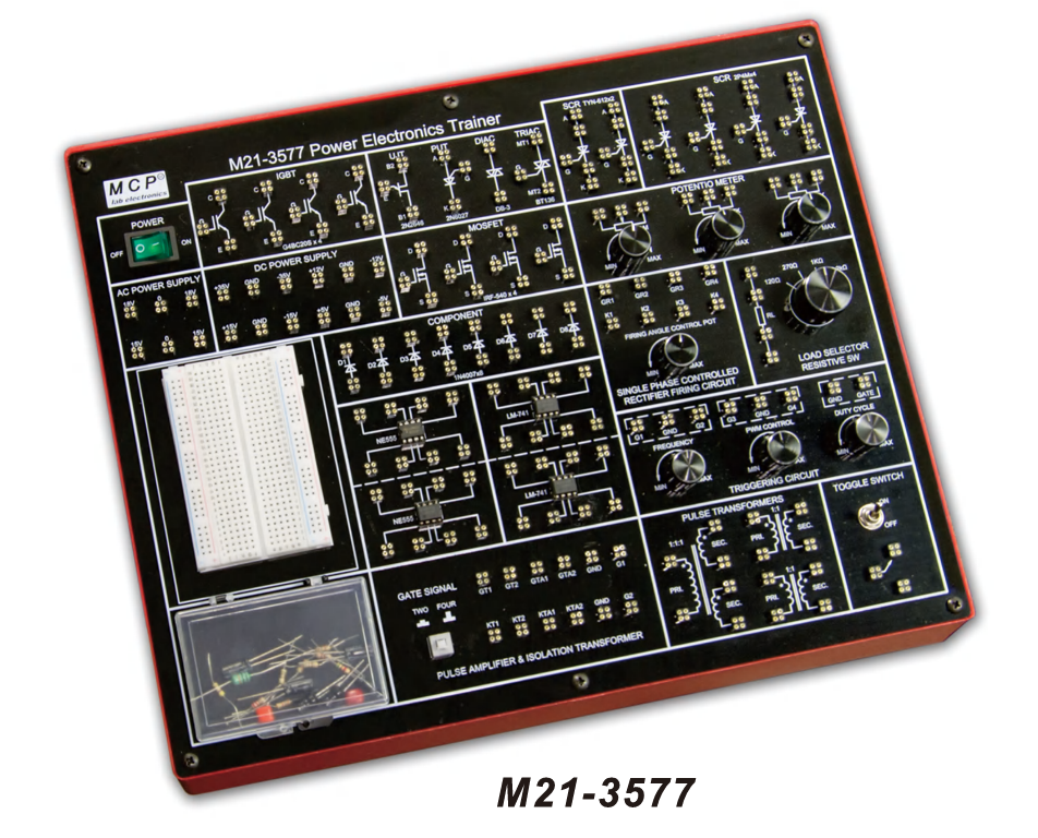
M21-3577 POWER ELECTRONICS TRAINER
BDT 41,145/-
Product Details
Brand: MCP
Model: M21-3577
Country Of Origin: China
Features
-
Comprehensive power electronics trainer
-
Study characteristics and applications of power devices
-
Perform essential power electronics circuit experiments
-
Integrated control panel for safe, easy operation
-
Reliable 4-point terminal connections
-
On-board element box with component set
Specifications (M21-3577)
-
Breadboard: 400 tie points (2 terminal strips, 2 distribution strips)
-
DC Power Supply: ±5V/200mA, ±12V/200mA, ±15V/200mA, ±35V/100mA
-
AC Power Supply: 18V–0–18V/200mA, 15V–0–15V/200mA
-
Triggering Circuit: 5 gate signal outputs, 40–900Hz variable, 12V amplitude, PWM duty cycle 0–100%
-
Single-Phase Rectifier: Firing angle control 0°–180°
-
Pulse Amplifier & Firing Circuit: 4 gate outputs with isolation
-
SCR Assembly: 2P4M ×4 (600V, 2A)
-
Power Devices: IGBT-G4BC20K ×4, MOSFET-IRF540 ×4, UJT-2N2646, DIAC-DB3, TRIAC-BT136, PUT-2N6027, SCR-TYN-612 ×2
-
Circuit Components: Diode-1N4007 ×8, NE555 ×2, LM741 ×2
-
Potentiometers: 4.7kΩ ×2, 1MΩ ×1
-
Load Resistors: 120Ω, 270Ω, 1kΩ, 2.2kΩ (5W)
-
Pulse Transformers: 1:1 ×2, 1:1:1 ×1
-
Toggle Switch: SPDT
-
Component Set: Resistors, capacitors, inductors, zener diodes (full list included)
-
Patch Cords: 20cm red/black ×10 each, 40cm red/black ×5 each
-
Input Voltage: 110–127VAC ±10% (60Hz), 220–240VAC ±10% (50Hz), switchable
-
Dimensions: 334×95×258mm
-
Weight: 4.5kg
Experiments Supported (30)
-
Device characteristics: SCR, UJT, MOSFET, IGBT, DIAC, TRIAC, PUT
-
Gate control and triggering circuits (resistor, RC, UJT, 555, Op-Amp)
-
Commutation circuits (Class B, C, D, E)
-
Oscillators: UJT relaxation, ramp/pedestal triggering
-
Inverters: phase commutated, Bedford, single-phase PWM (MOSFET/IGBT)
-
Rectifiers: half-wave, full-wave, bridge (resistive and RL loads)
| Breadboard: | 400 tie points (2 terminal strips, 2 distribution strips) |
| DC Power Supply: | ±5V/200mA, ±12V/200mA, ±15V/200mA, ±35V/100mA |
| AC Power Supply: | 18V–0–18V/200mA, 15V–0–15V/200mA |
| Triggering Circuit: | 5 gate signal outputs, 40–900Hz variable, 12V amplitude, PWM duty cycle 0–100% |
| Single-Phase Rectifier: | Firing angle control 0°–180° |
| Pulse Amplifier & Firing Circuit: | 4 gate outputs with isolation |
| SCR Assembly: | 2P4M ×4 (600V, 2A) |
| Power Devices: | IGBT-G4BC20K ×4, MOSFET-IRF540 ×4, UJT-2N2646, DIAC-DB3, TRIAC-BT136, PUT-2N6027, SCR-TYN-612 ×2 |
| Circuit Components: | Diode-1N4007 ×8, NE555 ×2, LM741 ×2 |
| Potentiometers: | 4.7kΩ ×2, 1MΩ ×1 |
| Load Resistors: | 120Ω, 270Ω, 1kΩ, 2.2kΩ (5W) |
| Pulse Transformers: | 1:1 ×2, 1:1:1 ×1 |
| Toggle Switch: | SPDT |
| Component Set: | Resistors, capacitors, inductors, zener diodes (full list included) |
| Patch Cords: | 20cm red/black ×10 each, 40cm red/black ×5 each |
| Input Voltage: | 110–127VAC ±10% (60Hz), 220–240VAC ±10% (50Hz), switchable |
| Dimensions: 3 | 34×95×258mm |
| Weight: | 4.5kg |
Features
-
Comprehensive power electronics trainer
-
Study characteristics and applications of power devices
-
Perform essential power electronics circuit experiments
-
Integrated control panel for safe, easy operation
-
Reliable 4-point terminal connections
-
On-board element box with component set
Specifications (M21-3577)
-
Breadboard: 400 tie points (2 terminal strips, 2 distribution strips)
-
DC Power Supply: ±5V/200mA, ±12V/200mA, ±15V/200mA, ±35V/100mA
-
AC Power Supply: 18V–0–18V/200mA, 15V–0–15V/200mA
-
Triggering Circuit: 5 gate signal outputs, 40–900Hz variable, 12V amplitude, PWM duty cycle 0–100%
-
Single-Phase Rectifier: Firing angle control 0°–180°
-
Pulse Amplifier & Firing Circuit: 4 gate outputs with isolation
-
SCR Assembly: 2P4M ×4 (600V, 2A)
-
Power Devices: IGBT-G4BC20K ×4, MOSFET-IRF540 ×4, UJT-2N2646, DIAC-DB3, TRIAC-BT136, PUT-2N6027, SCR-TYN-612 ×2
-
Circuit Components: Diode-1N4007 ×8, NE555 ×2, LM741 ×2
-
Potentiometers: 4.7kΩ ×2, 1MΩ ×1
-
Load Resistors: 120Ω, 270Ω, 1kΩ, 2.2kΩ (5W)
-
Pulse Transformers: 1:1 ×2, 1:1:1 ×1
-
Toggle Switch: SPDT
-
Component Set: Resistors, capacitors, inductors, zener diodes (full list included)
-
Patch Cords: 20cm red/black ×10 each, 40cm red/black ×5 each
-
Input Voltage: 110–127VAC ±10% (60Hz), 220–240VAC ±10% (50Hz), switchable
-
Dimensions: 334×95×258mm
-
Weight: 4.5kg
Experiments Supported (30)
-
Device characteristics: SCR, UJT, MOSFET, IGBT, DIAC, TRIAC, PUT
-
Gate control and triggering circuits (resistor, RC, UJT, 555, Op-Amp)
-
Commutation circuits (Class B, C, D, E)
-
Oscillators: UJT relaxation, ramp/pedestal triggering
-
Inverters: phase commutated, Bedford, single-phase PWM (MOSFET/IGBT)
-
Rectifiers: half-wave, full-wave, bridge (resistive and RL loads)
The M21-3577 Power Electronics Trainer is a complete educational platform for studying semiconductor devices and power circuits. Equipped with SCRs, TRIACs, DIACs, MOSFETs, IGBTs, and UJTs, it supports 30 experiments covering device characteristics, triggering methods, commutation techniques, oscillators, inverters, and rectifiers. With integrated DC/AC supplies, PWM triggering, and an onboard component set, the M21-3577 is ideal for engineering institutes, vocational schools, and research labs focused on power electronics education and development.
Asked by Visitor
100% Viscose Fabric.
Thank You.
Asked by Visitor