Description
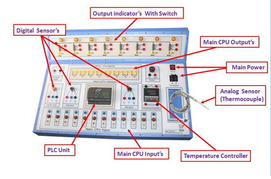
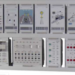
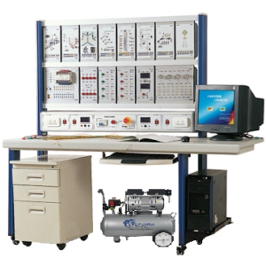
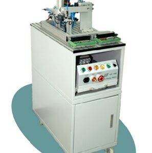
RAPT-301A, UNIVERSAL PLC TRAINER is a useful and user friendly trainer for understanding the concept of PLC. With the help of RAPT-301, PLC automation can be studied as well as analyzed. It helps to understand the PLC hardware, Relay, Sensor, Thermocouple, Magnetic contact etc. The trainer is based on diploma & B.Sc. in EEE & CSE) syllabus.
- Universal PLC Trainer
- Model: RAPT-301
- Main supply: Single Phase, 230V±10%, 50Hz, Output: 50W
- PLC: Siemens (1 Nos)
- PLC Input: 16 Nos
- PLC Ouput:12 Nos
- PLC Power supply (1 Nos)
- Input Voltage: 0-230V
- Output Voltage: 0, 18V, 24V
- Rated Current: 1A
- Digital Meters Used
- Voltmeter: 500V (1 Nos.)
- Temperature Controller: 0-400°C (1 Nos.)
- Thermo-coupler: 0-400°C (1 Nos.)
- Proximity Sensor (1 Nos)
- Photo Sensor (1 Nos)
- Output indicator: 220V (4 Nos)
- MCB (DP): 10A
- Size (L x W x H): 740 x 570 x 290 mm
- Weight: 20kg (approx.)
Scope of Learning
- Identify the parts and components of a PLC system (Relay, Photo Sensor, Proximity Sensor, Magnetic Contact, Temperature controller)
- The ability to connect input devices with PLC.
- The ability to connect output devices with PLC.
- Perform the tasks to develop and Simulate/execute a PLC ladder program (diagram) to start and stop a motor using two separate switches.
- Perform the tasks to develop and Simulate/execute PLC ladder program (diagram) using timer instructions.
- Perform the tasks to develop and Simulate/execute a PLC ladder program (diagram) using counter instructions.
- Perform the tasks to develop and Simulate/execute a PLC ladder program (diagram) using sequence instructions.
- Perform the tasks to develop and Simulate/execute a PLC ladder program (diagram) using arithmetic instructions.
- Perform the tasks to develop and Simulate a PLC ladder logic (diagram) to set both On-delay time and off delay time functions.
- Perform the tasks to develop and simulate PLC ladder logic (diagram) to control a push on/push off circuit.
- Perform the tasks to develop and simulate PLC ladder logic (diagram) to control a First –in-input priority circuit.
- Perform the tasks to develop and simulate PLC ladder logic (diagram) to control a Non–lock-in annunciation circuit.
- Perform the tasks to develop and simulate PLC ladder logic (diagram) to control a filling control circuit. (Optional)
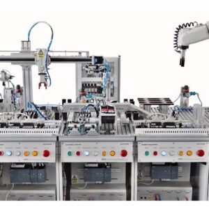
- Perform the tasks to develop and simulate PLC ladder logic (diagram) to control a Conveyor belt motor control circuit. (Optional)
- Perform the tasks to develop and simulate PLC ladder logic (diagram) to control a Boiler Temperature control circuit.
- Perform the tasks to develop and simulate PLC ladder logic (diagram) to control a Motor Using as Star Delta Starter.
- Perform the tasks to develop and simulate PLC ladder logic (diagram) to control a Object Shorting Circuit. (Optional)
- Perform the tasks to develop and simulate PLC ladder logic (diagram) to control a Traffic Light control circuit. (Optional)
- Perform the tasks to develop and simulate PLC ladder logic (diagram) to control a Fire Indication Control circuit. (Optional)
Output Module of PLC
Water Level Control Module:
Built-in 24V DC pump and power supply
4mm safety connector
Power Input:220VAC, 50/60Hz
Pump power: 5Watt
Pump Noise mode: Silent
Size (L x W x H): 640 x 320 x 440 mm
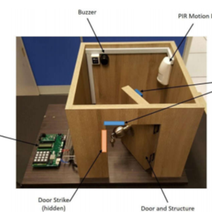
Fire Indication System Module:
Built-in 24V DC pump and power supply
4mm safety connector
Power Input:220VAC, 50/60Hz
Pump power: 5Watt
Pump Noise mode: Silent
Smoke sensor: 1EA
Ventilation Fan (12V,100mA): 4EA
Size (L x W x H): 740 x 380 x 420 mm
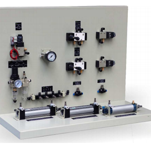
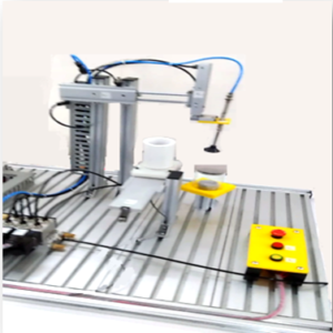
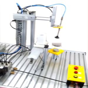
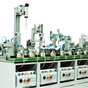
Automatic Pneumatic Control system:
Pneumatic cylinder: 3EA
Pneumatic solenoid valve: 3EA
Air compressor : 1 EA
PLC connection point : 1EA
Size (L x W x H): 700 x 350 x 740 mm
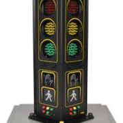
Traffic light control module:
Built-in 5V DC power supply
Power Input:220VAC, 50/60Hz
RED Indicator : 4EA
Yellow Indicator: 4EA
Green Indicator: 4EA


Reviews
There are no reviews yet.