

Description
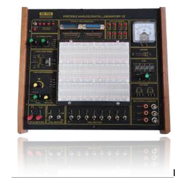
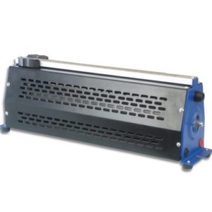
The AL-711A Portable Analog/ Digital trainer is an ideal teaching aid for all types of electronic circuits. Located all around the 2230 tie points removable breadboard is a variety of functional input and output circuits, which can be used to stimulate or measure electrical signals from the circuit under test or development. The removable breadboard area is not connected to these peripheral circuits and is meant to be connected by the user using standard solid AWG#22-30 wire. These circuit functions allow for the breadboarding and testing of circuits without the need for many expensive individual pieces of equipment.
Specification:
- Completely Self-Contained Unit
- Built in regulated D.C Supplies: +5V, 1.0A, -5V, 100mA Full Short circuit protection and indicators.
- Function generator: 1 KHz to 100 KHz continuously variable over 5 decade range. Sine Wave: variable 0 to ±4Vp-p, Triangle wave: 4Vp-p, Square wave: ±5Vp-p
- 3 State logic probe
- Two single shot pulse generator, 80µs
- 8 bit LED display with buffers
- 3.5 Digit digital voltmeter: 4 ranges-199.9mV, 1.999V, 19.99V and 199.9V fsd. LCD display input impedance: 4MΩ
- Analog current Meter: 0 to 100µA
- 2.5 inch 8Ω, 1 W loud speaker
- Two flip-flop gates-with mimic diagram
- Input /Output connectors BNC and Banana
- Two logic switches =5V/0V/-5V with Current limit
- 8 Data switches +5V/0V
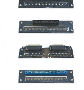
- Two 25 pin D type connectors for computer interface
- Removable breadboard with 2230 inter connected tie points, accepts 0-08mm solid ware.
Experiment Analog Circuits:
- The Superposition Theorem
- Capacitors in Voltage-Divider Networks
- Operational Amplifier- The Inverting Amplifier
- Operational Amplifier- The Non Inverting Amplifier
- Operational Amplifier- The Comparator
- Operational Amplifier- The Summing Amplifier
- The Common- Base Amplifier Structure
- The Common- Emitter Amplifier Structure
- The Common- Collector Amplifier Structure
- The Op amp Differentiator
- The Op amp Integrator
- The RC Phase Shift Oscillator
- The Astable Multi vibrator-555 Timer
- The Schmitt Trigger
- The Astable Multi vibrator
- The D/A Converter
- The A/D Converter
Experiment Digital Circuits:
- Fundamental Logic Gate- AND, OR, NOT
- Fundamental Logic Gate- NAND, NOR, XOR
- Applications of Boolean Algebra
- De Morgan’s Law -1
- De Morgan’s Law-2
- Diode Resistor Logic-AND
- Exclusive OR Using Basic Logic Gate
- Exclusive NOR Using Basic Logic Gate
- De-Multiplexer –Using the 74138 IC
- Synchronous Up- Counter
- Synchronous Down – Counter
- The Schmitt Trigger
- Oscillator – Using CMOS


Reviews
There are no reviews yet.